RIMFAX (Radar Imager for Mars' Subsurface Exploration)
mission specific
Instrument Overview
The RIMFAX (Radar Imager for Mars subsurFAce eXperiment) instrument and science investigation are more fully described in the publication "Radar Imager for Mars’ Subsurface Experiment – RIMFAX", Svein-Erik Hamran, David A. Paige, Hans E. F. Amundsen, Tor Berger, Sverre Brovoll, Lynn Carter, Leif Damsgård, Henning Dypvik, Jo Eide, Sigurd Eide, Rebecca Ghent, Øystein Helleren, Jack Kohler, Mike Mellon, Daniel C. Nunes, Dirk Plettemeier, Kathryn Rowe, Patrick Russell & Mats Jørgen Øyan, Space Science Reviews 216, Article Number 128 (2020). https://doi.org/10.1007/s11214-020-00740-4
In this section, a brief overview of the RIMFAX instrument is provided to familiarize the reader with the instrument’s primary functionality and operational implementation.
The principal goals of the RIMFAX investigation are to image the shallow subsurface structure beneath the rover and provide information regarding subsurface composition. The data provided by RIMFAX will aid the Mars2020 rover in its mission to explore the ancient habitability of its field area and to select a set of promising samples for caching and eventual sample return.
Instrument Operation
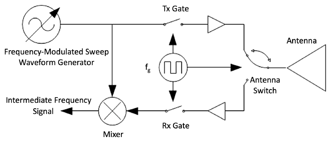
RIMFAX is a ground penetrating radar (GPR) that uses a single antenna to transmit (Tx) and receive (Rx) electromagnetic waves over a range of frequencies (150 to 1200 MHz) into/from the subsurface. A principle block diagram of the instrument is given in below. The instrument can be operated in either active (Tx and Rx) or passive (Rx-only) modes. Transmitted waves propagate downward until they are reflected back by shallow (≤ 10s of m) subsurface interfaces in geologic materials or structures, across which exist discontinuities in permittivity (the storage of electrical energy in an electric field).
Each sweep across the radar’s frequency range, or bandwidth, produces a radar measurement known as a “sou nding”. A raw FMCW RIMFAX sounding is a record of the reflected power returned at each frequency over the bandwidth. A processed RIMFAX sounding, more analogous to most terrestrial-use GPRs, is a time series of the reflected power. The receival time of each sample is related to the position in the subsurface from which the received power was reflected. The RIMFAX instrument paper [10] describes this relationship, which is largely modulated by the velocity of the signal in the medium, in turn influenced by the material’s dielectric and physical properties. As the rover (and RIMFAX) moves along its traverse path, successive soundings are taken at fixed increments of distance along the surface. The 2-D display of these soundings according to their acquisition location is an image known as a “radargram”, with distance along the traverse increasing towards the right, and time (related to depth, as above), increasing downwards. Measurements can also be made while the rover (and RIMFAX) is stationary with respect to the surface, and successive co-located stationary soundings can build a time series. Such a dataset may capture how the dielectric properties of the surface/subsurface at that individual location may change over a given period (e.g., in response to thermal influences).
To properly convert the vertical dimension from the time delay, t, to depth, d, it is necessary to apply values of permittivity, e, to the subsurface to correct for the speed of light in the medium as follows:
d = v * t,
where:
v = c / sqrt(e).
Further, ancillary navigation data from the rover are necessary to determine the location of each sounding.
Waveform
RIMFAX uses a Frequency Modulated Continuous Wave (FMCW) waveform. In FMCW radar the baseband signal is low-pass filtered before being sampled. This filter effectively removes deeper reflectors and yields an ambiguity-free range interval. The RIMFAX FMCW waveform uses a gating technique that allows a single antenna to be used both as a transmitter and receiver.
The working principle of an FMCW radar is illustrated in the figure below.
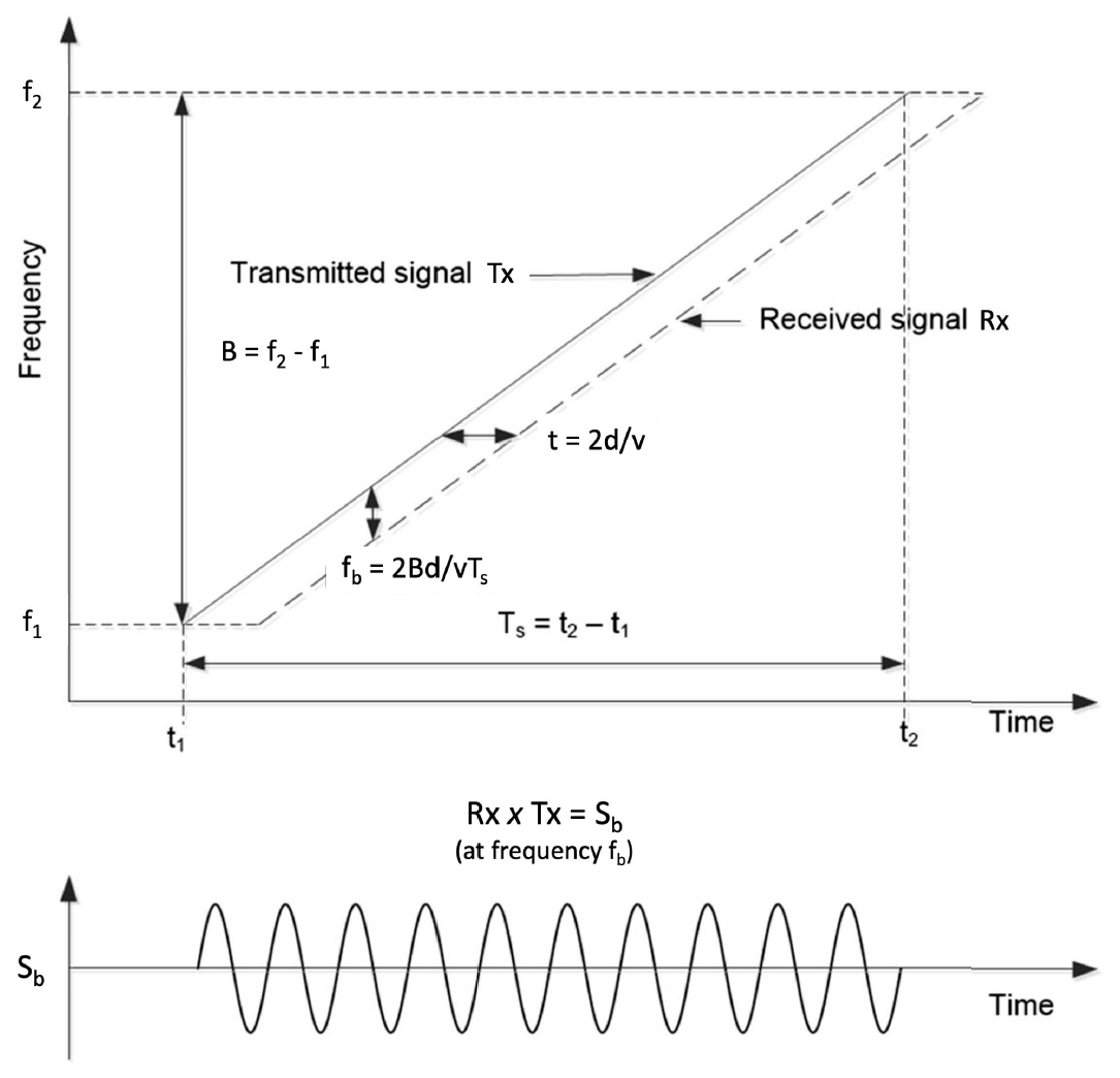
A signal, Tx, is swept through the full bandwidth, B, of frequencies (from f1 to f2) over the time span, Ts (from t1 to t2), and is transmitted through the antenna (as represented by the solid line Tx). A signal reflected from a distance, d, is received by the antenna delayed by the two-way travel time, t, equal to 2d/v, where v is the wave velocity in the material. This delayed received signal, Rx, has a different frequency than the signal currently being transmitted (represented by the dashed line Rx). Multiplying the received signal with the signal currently being transmitted gives a baseband signal, Sb = Rx x Tx. At any point in time, this baseband signal has a frequency equal to the frequency difference between the transmitted and received signals. For a stationary reflector this frequency difference is constant over the sweep. The frequency of this constant baseband signal, called the beat frequency, fb, is proportional to the delay time, t, and thereby to the distance range, expressed as 2d/v, to the reflector. The proportionality constant is given by the ratio between the sweep bandwidth and the duration of the sweep, or B/Ts. The frequency of the beat signal is thus:
fb = 2Bd / vTs
Measuring the beat frequency thus yields the range to the reflector. The amplitude of the received sine-wave signal gives the reflection strength. If several reflectors are present the baseband signal will be a summation of all the different reflected signals. Spectral estimation techniques like Fourier transforms can calculate the reflected signal.
Gating
The FMCW signal is gated in a switch before being amplified and fed to the antenna through the antenna switch. The gating switches the FMCW signal on and off with a duty cycle up to 50%. The gating frequency is much lower than the transmitted-signal frequency and higher than the baseband signal spectrum. The reflected signal response will be a convolution between the gated, square-wave transmitted signal and the square wave of the receiver gating. This response function will be a triangular waveform producing an effective linear gain on the received signal as a function of depth. Typically the maximum of the gating function will correspond to the maximum instrumented range. After the gating peak a linear reduction in amplitude will be combined with the spherical loss and attenuation in the media reducing the reflected signal rapidly.
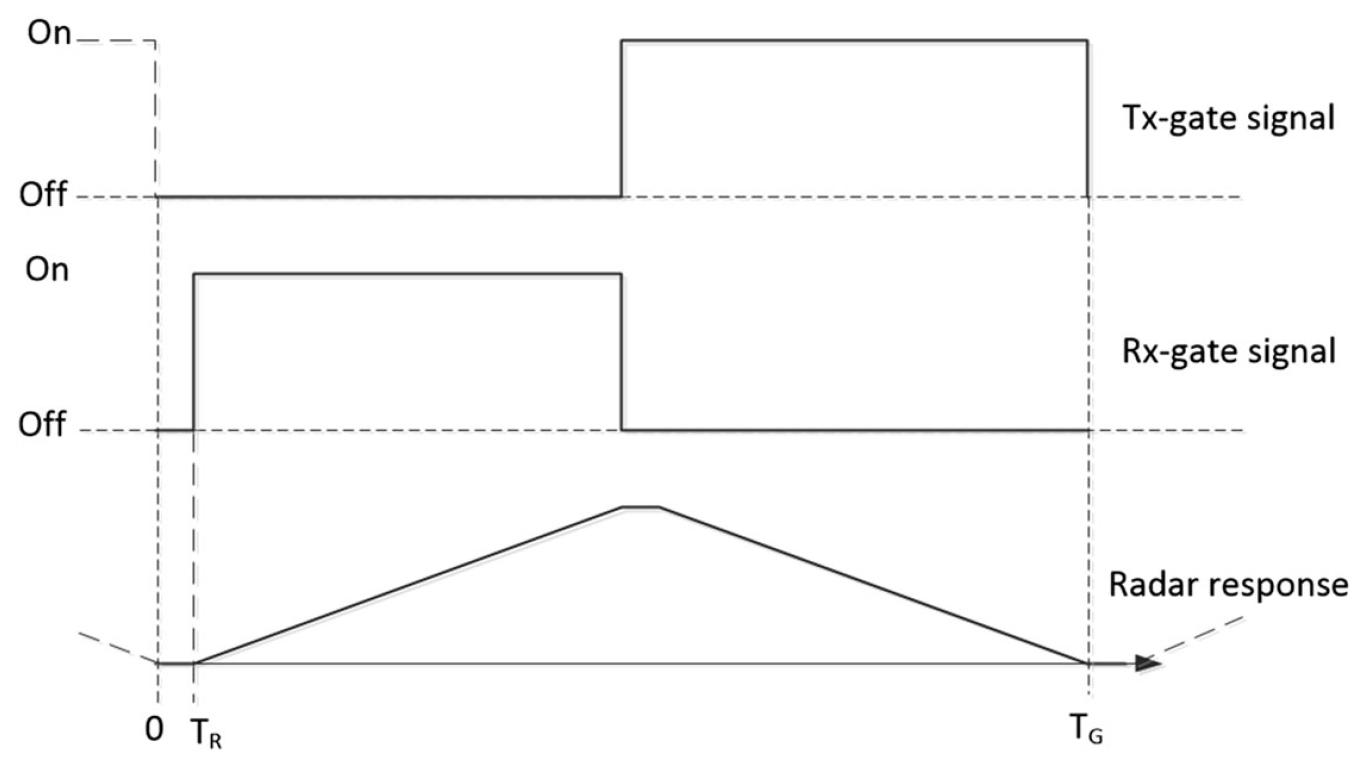
If the receiver gating waveform is turned on with a slight delay after the transmitter gating signal turns off, there will be a time window where no signal is entering the receiver. This is illustrated in the figure below, in which the receiver gate signal delay time is represented by TR. Any reflected signal from the exterior or subsurface that arrives during the time-delay window from 0 to TR does not enter the receiver. The radar response as a function of time will then be a symmetric triangular shape with a flat-peaked top of time-length TR, giving a linear gain with travel time and depth. If the frequency of the square wave gating signal is FG , then the total gating window length in time is:
TR = 1 / FG
The gating makes it possible to remove strong reflectors from the receiver signal before the signal is digitized, effectively increasing the dynamic range coverage of the radar system.
Calibration cable
The RIMFAX electronics unit has two different outputs for transmitting the FMCW signal: an antenna port, where the antenna is connected via the antenna cable running through the rover bulkhead, and the calibration port, where a 2.8-m calibration cable is connected. The calibration cable is placed close to the RIMFAX electronics, inside the rover, and is shorted at the end to produce a reflection from the end of the cable. An electronic switch controls whether the calibration cable or the antenna is used.
The main purpose of the calibration cable is to provide measurements of gain variations in the transmitter and receiver. During operations on Mars the calibration cable measurements will be performed at specific distances during a traverse, for example every 10 meters, or at specific time intervals during stationary activities, for example every hour. The reflected signal from the calibration cable termination will be used to calibrate for temperature-dependent variations in radar amplitude and timing.
Surface Operation
RIMFAX is designed to operate in different modes in which radar parameters are set to optimize data collection for different subsurface conditions and depths. The RIMFAX gating makes it possible to omit the recording of close-range reflections, typically from the antenna and surface, which would otherwise limit the dynamic range. The removal of these reflections makes it possible, when desired, to increase the radar’s gain to capture weak subsurface reflections. Shifting the receiver dynamic range window particularly to each mode effectively increases the radar’s total dynamic range when soundings from different modes are considered together.
1. Surface Mode
The antenna reflection is captured in the receiver window.
Measures the surface reflection and the very upper subsurface only.
2. Shallow Mode
The antenna reflection is removed from the receiver window.
Measures the surface reflection and the shallow subsurface.
3. Deep Mode
The antenna and surface reflections are removed from the receiver window.
Measures reflections from the upper subsurface (~1 m depth) through the instrumented range.
Together, these modes extend the dynamic range of RIMFAX up to 62 dB above the dynamic range of a single mode, giving an approximate total dynamic range of 160 dB. For stationary measurements, the dynamic range can be further increased by doing a Long Integration Sounding (LIS), in which a few to several hundred soundings are summed together (on the rover RCE) to increase the processing gain.
Instrumented range and resolution can also be selected within each mode to optimize measurements based on subsurface composition and penetration depth. This is accomplished by choosing combinations of frequency range (i.e., bandwidth) and sweep time of the waveform over the frequency range, which also results in different data volumes. The table below gives the RIMFAX instrumented range (in free space) as a function of bandwidth and sweep time. Data volume per sounding given for each sweep time.
| Sweep time [ms] | |||||||||
|---|---|---|---|---|---|---|---|---|---|
| 100 | 50 | 25 | 12.5 | 6.25 | 3.125 | 1.5625 | 0.78125 | ||
| Bandwidth [MHz] | 450 | 947 m | 486 m | 242 m | 120 m | 59 m | 28 m | 13 m | 5.4 m |
| 750 | 583 m | 291 m | 144 m | 71 m | 34 m | 16 m | 6.96 m | 2.3 m | |
| 1050 | 416 m | 207 m | 102 m | 50 m | 24 m | 11 m | 4.3 m | 1 m | |
| Data volume [bytes] | 19530 | 9764 | 4882 | 2440 | 1220 | 610 | 304 | 152 | |
Typically, a high resolution using the full bandwidth is selected in the shallow mode, when most frequencies will be able to penetrate to the full, shallow instrumented range. In the deep mode, a narrower bandwidth limited to the lower part of the frequency range is used, and there is a tradeoff between data volume (based on number of samples per sounding) and penetration depth. Choices of sweep time are limited to the 8 values in Table 5. Bandwidth can be set between 0 and 1050 MHz (i.e., not limited to values in Table 5) within the frequency range 150-1200 MHz.
For sweep times less than 100 ms, sweeps are repeated and signal is averaged until the total collection time period reaches 100 ms. This practice ensures that the processing gain is equal for each sounding, independent of radar configuration.
The nominal plan for operation on Mars is to collect soundings from each of three modes every 5-10 cm along the rover traverse, During a drive, the distance the antenna has moved is determined and tracked solely by the FM, with no memory, modifications, or correction by RIMFAX. When the tactically planned interval distance (since the previous measurement) has been attained as the rover moves along its path, the RIMFAX Instrument Manager (RIM) on the Rover Computer Element (RCE) commands RIMFAX to make the subsequent measurement.
In addition to nominal, active operation, RIMFAX can be operated in passive modes with the transmitter off but the receiver on, connected to either the antenna or the calibration cable. An ambient spectrum can be measured through the antenna, or an estimation of self-induced noise can be made with the calibration cable and used as an input to signal processing to increase system performance.